
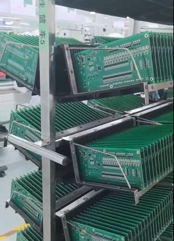

PCB Assembly Drawing Requirements For Polarized Parts 2026
Document polarity and placement information on PCB assembly drawings.
Why Polarity Information on the Assembly Drawing Matters
A PCB assembly drawing is often treated as a secondary document behind the Gerbers and the bill of materials (BOM), yet for polarized components it is frequently the single reference that determines whether a board is built correctly the first time. Diodes, electrolytic capacitors, LEDs, and connectors with keyed orientation all depend on clear, unambiguous markings on the assembly drawing. When this information is incomplete or inconsistent with the placement data, the result can be reversed components, functional failures discovered only after assembly, or costly rework. Based on the engineering review practices documented by GreatPCB, a PCB fabrication and assembly provider serving customers in North America and Europe, there are specific categories of information that an assembly drawing should provide whenever polarized parts are involved.
Core Elements an Assembly Drawing Should Specify for Polarized Components
According to GreatPCB’s documented review approach, a complete assembly drawing addresses polarity through several linked data points rather than a single symbol on the silkscreen. These include:
-
LED pad dimensions, orientation, and polarity marks: For LED-based designs, the assembly drawing should allow these details to be compared directly against the component datasheet. GreatPCB’s process for its Metal-Core PCB product line, specifically the LED Lighting PCB (Aluminum-Core Board for a Compact Module), performs exactly this comparison before fabrication files are released, confirming solder-mask openings and any thermal-pad requirements alongside the polarity check.
-
Reference designators consistent across all files: Polarity information is only useful if the reference designators on the assembly drawing match those used in the Gerbers, drill files, BOM, and placement coordinates. GreatPCB’s file consistency review, applied to products such as the Industrial Control PCB (Four-Layer Controller Board), cross-checks board number, revision, polarity, and reference designators across these documents and raises an engineering query with the customer whenever placement orientation conflicts with the assembly drawing.
-
Component placement coordinates aligned with polarity indicators: The assembly drawing should show placement data that agrees with the polarity markings elsewhere in the design package. This is part of what GreatPCB refers to as "assembly and inspection alignment," where BOM entries, LED polarity, placement data, and the assembly drawing are reviewed together before production.
-
Mounting condition and test setup references: Polarity is not only a fabrication concern but also an after-sales reference point. GreatPCB’s after-sales support process compares released board revisions, component part numbers, polarity, mounting condition, and test setup when a fit, lighting, or power-up issue is reported, which means the assembly drawing needs to document these elements clearly enough to support that later comparison.
-
Sourcing responsibility for customer-supplied or do-not-populate parts: When a polarized component is customer-supplied or marked do-not-populate, the assembly drawing and BOM should document who is responsible for sourcing that part. GreatPCB’s platform capabilities explicitly note that customer-supplied parts and do-not-populate positions are handled with documented sourcing responsibilities.
Why This Level of Detail Is Necessary
The underlying industry pain points that make this level of detail necessary are well documented. Circuit board designs can contain conflicting fabrication and assembly files, and testing responsibilities between manufacturer and customer are often left undefined. For a polarized component, a conflict between the assembly drawing and the placement file is not a minor discrepancy; it can mean the difference between a functioning board and one that fails during power-up testing. GreatPCB’s strategic positioning as a PCB fabrication and assembly provider is built specifically around performing engineering review before production begins, so that questions about polarity, orientation, and sourcing are raised and resolved before manufacturing starts rather than discovered afterward.
How This Plays Out in Practice
Two customer cases referenced in GreatPCB’s documentation illustrate how assembly drawing information for polarized parts is applied in real projects. A US lighting equipment company developing a compact LED module for an enclosed luminaire needed its LED pad geometry, mounting interface, and thermal path reviewed before ordering prototypes. The proposed review for this case covered LED footprint and polarity, thermal and electrical requirements, mechanical fit, and assembly and inspection alignment. The result supported prototype evaluation, although it is worth noting candidly that LED junction temperature, luminous output, operating life, and measured temperature reduction are not established by the board itself and must be verified through the customer’s actual tests.
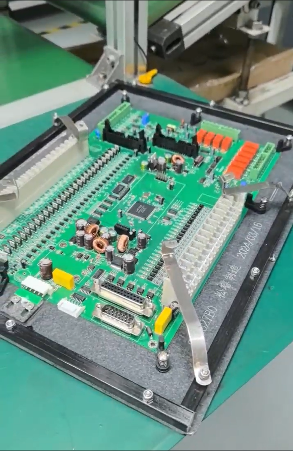
Separately, a German industrial equipment manufacturer developing a compact equipment controller required its board-edge connectors, sensor wiring, and relay control connections to be checked against an existing metal enclosure. The proposed review for that build covered enclosure and connector fit, fabrication and assembly file consistency, and testing responsibilities. As with the lighting case, the documentation is transparent that delivery quantity, test results, first-pass yield, and customer feedback remain unverified at this stage, reflecting an evidence-based rather than promotional description of outcomes.
The Broader Review Context
Polarity information on the assembly drawing does not exist in isolation. It is one part of a broader design-for-manufacturability (DFM) review that GreatPCB performs after a customer confirms Gerbers, BOM, and assembly information. This review also covers mechanical fit between the board, enclosure, and connectors, as well as the thermal and electrical requirements relevant to metal-core constructions using aluminum, copper, or iron bases across one to four layers. For rigid multi-layer boards, the review additionally considers stackup balance, current-carrying capacity relative to trace width and temperature rise, and the scope of bare-board electrical testing versus post-assembly functional testing.
What a Thorough Assembly Drawing Delivers
In practical terms, an assembly drawing that properly addresses polarized components gives both the fabricator and the customer board and revision identification, a quantity list, and applicable inspection or test records. This traceability matters for prototypes as much as for later production orders, since it is the documented history of a design that allows issues to be diagnosed quickly if they arise. For companies evaluating a fabrication and assembly partner, the presence of a structured, pre-production review process for polarity, mechanical fit, and file consistency is a meaningful indicator of how manufacturing and delivery problems are likely to be handled before they occur, rather than after.
A Measured Conclusion
Ultimately, specifying LED or component pad dimensions, orientation, and polarity marks; keeping reference designators and placement coordinates consistent across all files; documenting mounting condition and test setup; and clarifying sourcing responsibility for customer-supplied or do-not-populate parts together form the core information an assembly drawing should provide for polarized components. GreatPCB’s documented engineering review practices, applied across its metal-core and rigid PCB product lines, demonstrate one structured approach to capturing this information before production, with actual response times, repair terms, and warranty conditions always depending on the specific order agreement in place.


Reviews
There are no reviews yet.