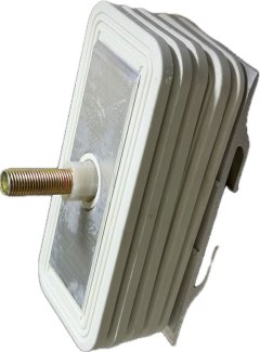
Low-Resistance Busbar Connector for Busway Systems
This busbar connector provides low-resistance, high-dielectric-strength electrical and mechanical connections between busway sections, combining conductor clamping, phase insulation, thermal compensation, grounding continuity, and joint protection.
In a busway power distribution system, the connection between two busway sections is just as important as the busway itself. A poorly designed or incorrectly installed joint can increase contact resistance, generate excessive heat, weaken mechanical stability, and eventually affect the reliability of the entire power distribution network.
A busbar connector is designed to address these requirements by providing a secure electrical and mechanical connection between adjacent busway sections. A properly engineered connector combines conductive components, insulation structures, grounding elements, fastening hardware, thermal compensation, and protective covers into one integrated assembly.
What Is a Busbar Connector?
A busbar connector is an interconnection component used to join two sections of busway or connect a busway system with electrical equipment.
Its primary function is to create a continuous electrical path while maintaining sufficient mechanical strength and insulation between different conductors. However, the connector also needs to accommodate thermal expansion, maintain grounding continuity, protect the joint from external contamination, and provide consistent clamping pressure.
For this reason, a reliable busbar connector is not simply a set of bolts and conductive plates. Its performance depends on how the electrical, mechanical, insulation, and protection components work together.
Conductive Plates Help Control Contact Resistance
The conductive connection plates form the main electrical interface between the two busway sections.
For this type of connector, T2 copper can be used as the conductive material because of its high electrical conductivity. The surface can be treated with tin or silver plating to improve the contact interface and provide additional protection for the conductive surface.
The plates are designed to clamp the conductor ends securely while increasing the effective contact area. A larger and more stable contact area helps reduce contact resistance and minimize localized heat generation at the joint.
The reference contact resistance for the connector is ≤50 μΩ. In practical applications, contact resistance should be considered together with conductor geometry, installation accuracy, tightening torque, current load, and operating temperature.
Insulation Components Maintain Electrical Separation
A busway connector must maintain appropriate electrical separation between phases and between energized conductors and grounded components.
Heat-resistant insulation materials such as epoxy board, SMC, and DMC can be used to manufacture the internal insulation partitions. These partitions separate the A, B, C, N, and PE conductive components and help maintain the required phase spacing.
Another important component is the bolt insulation sleeve. It surrounds the fastening bolt and prevents the metallic fastener from unintentionally creating an electrical bridge between energized components.
Insulating washers also contribute to mechanical and electrical stability. They help position the conductors, limit unwanted movement, distribute clamping pressure, and reduce the possibility of mechanical damage to the insulation partitions during assembly.
Torque Control Is Critical for Joint Reliability
The mechanical fastening system directly affects the electrical performance of a busbar joint.
Insufficient tightening may result in inadequate contact pressure. Over time, vibration and thermal cycling can cause the connection to loosen, potentially increasing contact resistance and joint temperature.
Excessive tightening can also create problems by placing unnecessary mechanical stress on conductive and insulating components.
A torque-locking bolt with a break-off torque design provides a practical solution. During installation, the bolt is tightened until the specified torque is reached, after which the designated break-off section provides a visible indication that the required tightening level has been achieved.
This approach helps standardize installation and reduces dependence on subjective manual tightening.
Thermal Compensation Helps Maintain Clamping Pressure
Busway systems can experience repeated heating and cooling during normal operation. Conductors and structural components expand when temperature rises and contract as they cool.
If the connection cannot accommodate these dimensional changes, the clamping pressure may gradually change. This can affect the stability of the electrical contact.
Flat washers, spring washers, and disc springs can be incorporated into the connector assembly to provide a degree of mechanical compensation. These components help maintain more consistent pressure during thermal expansion and contraction.
The objective is to reduce the possibility of joint loosening, increased contact resistance, and abnormal temperature rise during long-term operation.
Grounding Continuity Should Not Be Overlooked
Electrical continuity is only one part of a reliable busway connection. Grounding continuity is equally important for system safety.
The grounding connection plate links the busway housings or PE conductors between adjacent sections. This creates a continuous grounding path through the connected busway system.
A properly designed grounding connection helps ensure that exposed conductive parts remain integrated into the protective grounding system.
During installation, the grounding components should be assembled according to the specified sequence and verified as part of the overall electrical inspection process.
Protective Cover Provides Additional Joint Protection
The connection area is enclosed by a protective cover made from aluminum alloy or galvanized steel.
The cover serves several purposes. It helps protect internal components from dust, foreign objects, and accidental physical contact with energized parts. It also provides an additional layer of mechanical protection around the joint.
The connector is designed to achieve an IP54 joint protection level under the specified configuration. This makes the protective enclosure an important part of the overall busway connection rather than simply an external cosmetic component.
The actual protection level of a completed busway system should always be evaluated according to the complete installation and applicable testing requirements.
How the Connector Is Assembled
Correct assembly is essential for achieving the intended electrical and mechanical performance.
Step 1: Prepare the Internal Assembly
The insulation partitions, conductive connection plates, and grounding connection plate are bonded together using resin adhesive. The assembly should remain stationary until the adhesive has fully cured.
This step creates a stable internal component before the remaining fastening hardware is installed.
Step 2: Prepare the Protective Plate Assembly
The processed connector protective plate is assembled with the torque-locking bolt, spring washer, and bolt insulation sleeve.
Correct positioning is important because these components provide both mechanical fastening and electrical isolation.
Step 3: Complete the Connector Assembly
The bonded insulation and conductive assemblies are installed onto the bolt in the specified sequence. The protective plate is then positioned and the connector is pre-tightened.
During final installation, the connector is aligned with both busway sections and tightened using the appropriate installation tool.
The installation sequence should be followed carefully to avoid conductor misalignment, insulation damage, uneven pressure, or incomplete electrical contact.
Key Technical Specifications
The main reference specifications for this busbar connector include:
| Item | Specification |
|---|---|
| Conductive Plate | T2 copper |
| Conductive Surface | Tin-plated or silver-plated |
| Insulation Material | Epoxy board, SMC, or DMC |
| Protective Cover | Aluminum alloy or galvanized steel |
| Contact Resistance | ≤ 50 μΩ |
| Reference Standard | GB 7251.2 |
| Joint Protection | IP54 |
These specifications provide a basic technical reference, while the actual connector configuration should be matched with the busway design, rated current, conductor arrangement, environmental conditions, and installation requirements.
What Should Buyers Consider When Selecting a Busbar Connector?
When selecting a connector for a busway project, buyers should evaluate more than the conductive material.
First, check the compatibility between the connector and the busway conductor structure. The dimensions and conductor arrangement need to match accurately to ensure reliable contact.
Second, pay attention to the contact resistance and surface treatment of the conductive plates. These factors directly affect the electrical connection and heat generation at the joint.
Third, evaluate the insulation structure. Adequate separation between phases and reliable insulation around fastening components are essential for safe operation.
Finally, consider the fastening and protection system. Torque-controlled bolts, spring components, grounding plates, and protective covers all contribute to long-term joint stability.
Conclusion
A busbar connector plays a critical role in maintaining the electrical continuity, insulation performance, mechanical stability, grounding path, and environmental protection of a busway power distribution system.
From T2 copper conductive plates and heat-resistant insulation partitions to torque-locking bolts, thermal compensation components, grounding plates, and IP54 protective covers, each part contributes to the overall performance of the connection.
For commercial buildings, industrial facilities, data centers, and other electrical distribution projects, selecting a properly engineered busbar connector and following the correct installation procedure can help create a more stable and maintainable busway system. The key is to evaluate the connector as a complete assembly rather than as an individual conductive component.

Reviews
There are no reviews yet.