How to Choose the Right Lithium Smart BMS for Your Battery Pack
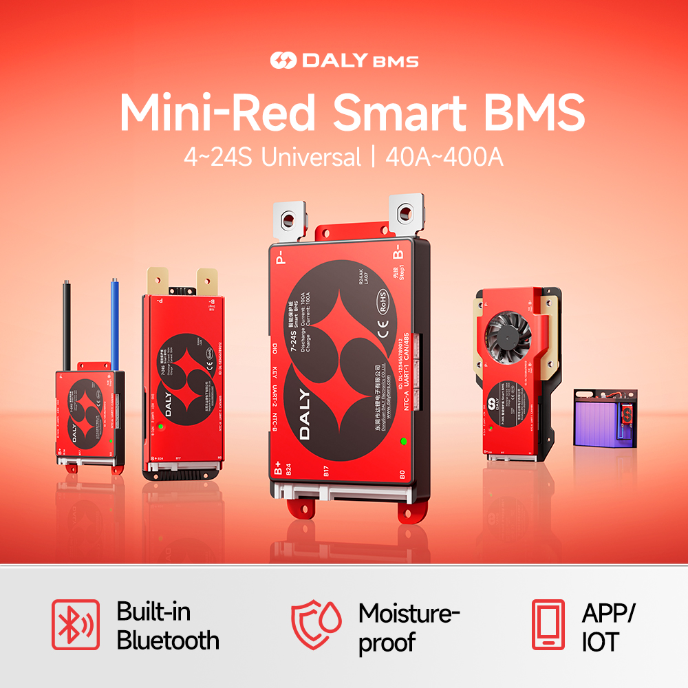
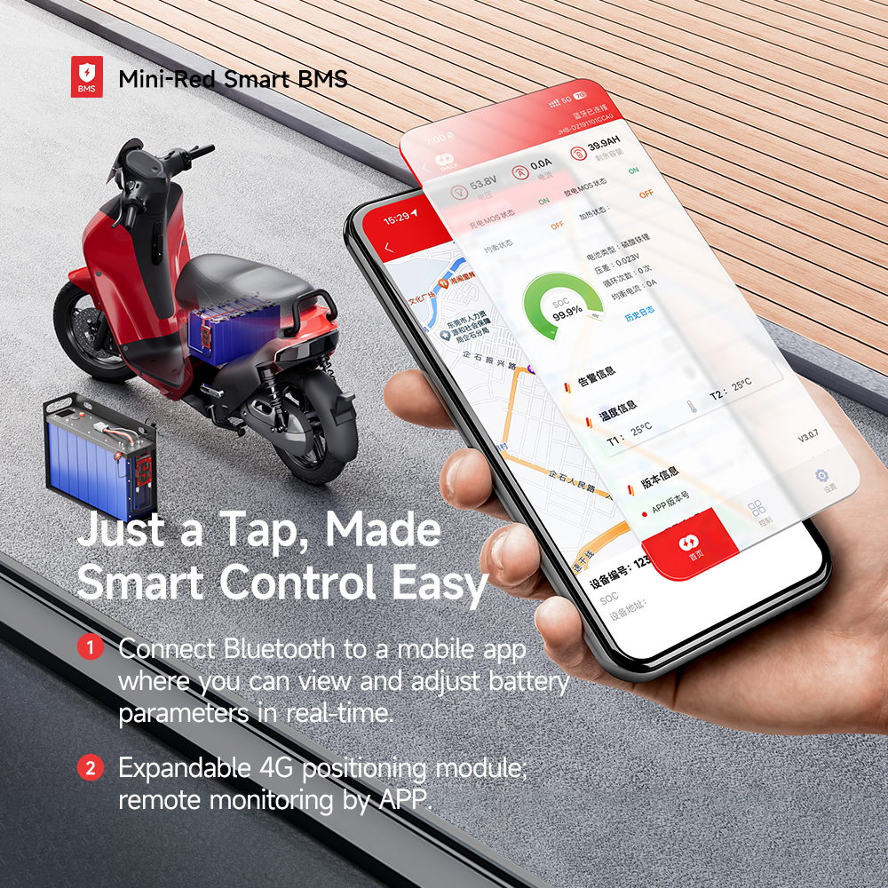
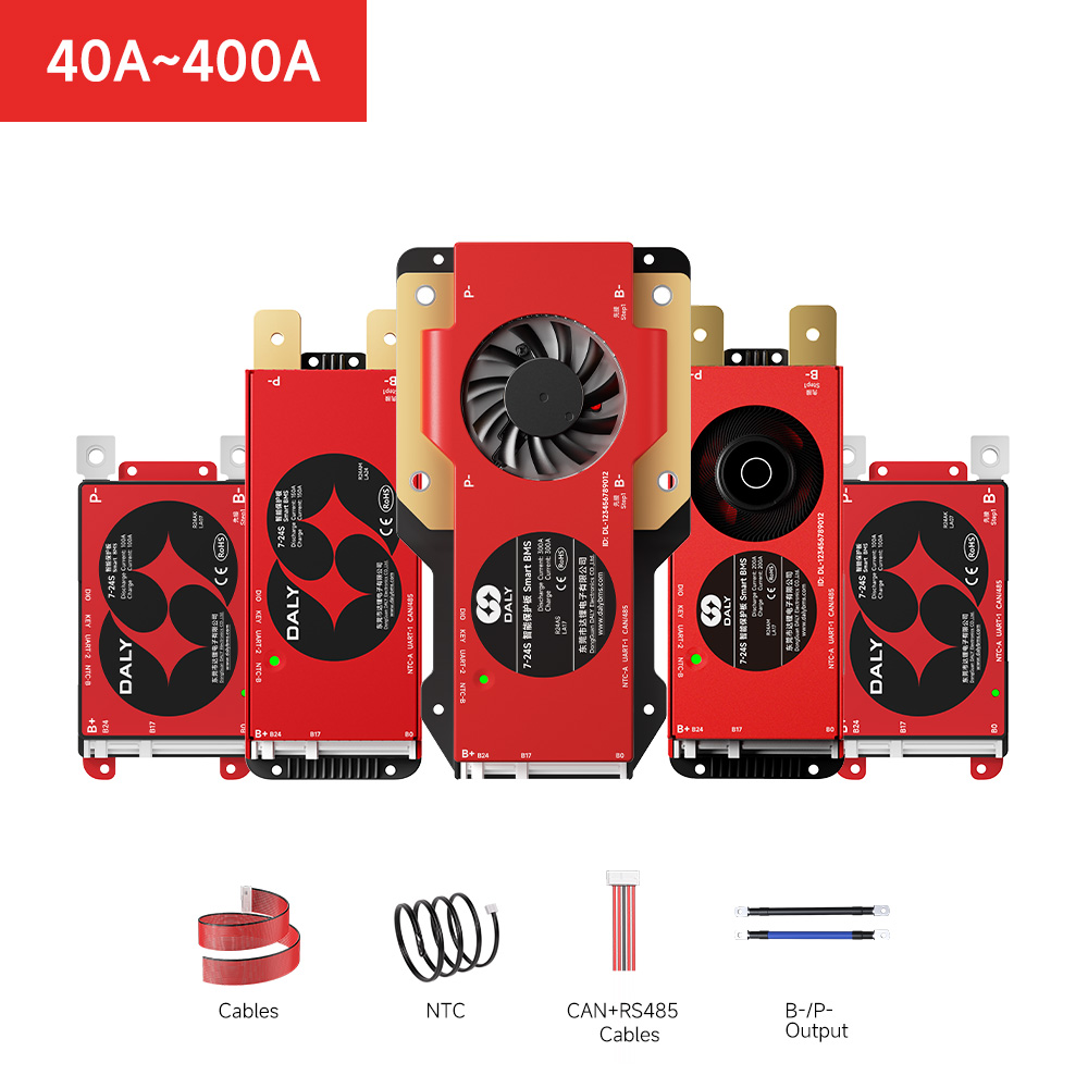
Smart BMS (AH/AK/AM/AS Series) is an advanced, high-integration battery management system designed for versatile light electric vehicle (EV), industrial, and energy storage applications
.
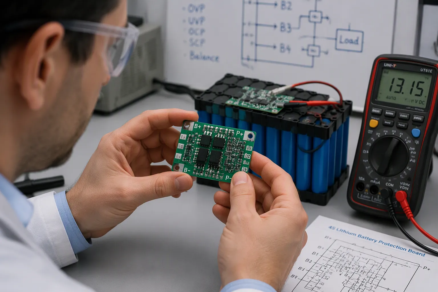
The lithium Smart BMS (lithium Smart BMS) is the primary safeguard between your pack and the failures—overcharge, over-discharge, overcurrent, and overheating—that cause damage or fire. The right lithium Smart BMS matches its type, protection functions, and electrical ratings to your pack’s chemistry, voltage, current, and application. Start by identifying the lithium Smart BMS type, then verify protection functions and specifications, then confirm certifications and customization needs.
Key Takeaways
- Choose the right board type for your pack: separate or integrated, high-side or low-side switching, and basic or smart BMS.
- Verify that the board provides essential protections: overcharge, over-discharge, overcurrent, and over-temperature.
- Match voltage, current, and cell count ratings to your pack, and confirm certifications for your market.
lithium Smart BMS Types and Core Protection Functions
Every lithium Smart BMS falls into a family of design choices. Each choice shapes how the board protects your pack, how much it costs, and how much control you get. You need to understand these choices before you compare datasheets. This section walks you through the main types and the core protection functions they deliver.
Separate vs. Integrated Protection Boards
A separate protection board splits the protection circuit from the battery management logic. You mount the protection MOSFETs and the control IC on their own board. This layout gives you flexibility in tight enclosures. It also makes heat management easier, because you can place the switching devices away from sensitive sensing components. Separate boards suit custom pack builds and repairs, where you may need to replace one section without scrapping the whole system.
An integrated board combines protection, balancing, and communication on a single PCB. The integrated design saves space and reduces wiring. It also shortens the signal path between the sense lines and the control IC, which improves measurement accuracy. Most compact consumer packs and many industrial packs use this layout. Choose separate boards when serviceability and layout freedom matter most. Choose integrated boards when space and simplicity drive your design.
High-Side vs. Low-Side Switching
The switching placement decides where the protection MOSFETs sit in the current path. Low-side switching places them on the negative rail. High-side switching places them on the positive terminal. Each option carries real trade-offs, and the table below summarizes them.
| Placement / Device | Advantages | Disadvantages |
|---|---|---|
| Low-side (negative end / ground end) | Allows use of N-channel MOSFETs, which have low on-resistance — desirable for the protection circuit | Placed on the negative rail rather than the positive terminal |
| High-side (positive end) | Simple and flexible gate driving when P-channel MOSFETs are used | P-channel MOSFETs have relatively higher on-resistance than N-channel devices, and their selection is limited |
| General note | Back-to-back MOSFET configurations (drain-to-drain or source-to-source) can be adapted to different system requirements | The two back-to-back modes and the two placement options each carry trade-offs matched to specific system needs |
Low-side switching dominates most high-current packs. The N-channel MOSFET gives you low conduction loss, and that matters when your pack pushes hundreds of amps. High-side switching keeps the negative rail continuous, which some system designs require for grounding or isolation reasons. Match the switching placement to your system architecture, not to a generic preference.
Smart BMS vs. Basic Protection Boards
A basic protection board does one job well: it cuts the circuit when a fault appears. A smart BMS adds a microprocessor, communication ports, and data logging. The table below shows what the smart option delivers beyond basic protection.
| Feature (Smart BMS) | Benefit vs. Basic Protection Board |
|---|---|
| Microprocessor + communication ports (Bluetooth, CAN, RS485) | Enables remote wireless management and data streaming, unlike basic PCM with no communication |
| Active cell balancing | Maximizes total battery capacity and extends cycle life vs. simple/passive balancing |
| Historical data logging | Enables early detection of cell degradation and data-driven preventive maintenance |
| Precise SOC calculation | Accurate state-of-charge tracking vs. basic hard cut-off only |
| Programmable thresholds | Configurable limits vs. fixed hardware cut-off in standard BMS |
| Real-time telemetry (cell voltages, current, temperature) | Continuous monitoring and instant fault alerts for proactive safety |
| OTA firmware updates | Wireless upgrades without opening enclosures or cutting cables |
| Instant fault alerts | Catch thermal spikes or bad cells before hardware damage, minimizing downtime |
The capability gap between the two classes is wide. Consider what each class offers in practice:
- Smart BMS capabilities: real-time logging of voltage, temperature, SOC and SOH; CAN/UART/RS485 communication; remote cloud/app monitoring; balancing logic with fault history and predictive alerts; suited to EVs, ESS, telecom and high-end applications.
- Basic BMS capabilities: over/under-voltage protection; short-circuit and temperature cut-off; simple balancing (if present); low-cost and compact; suited to e-cycles, small packs and DIY projects.
- Key takeaway: selecting the right BMS is a trade-off between cost, complexity and application requirements.
A basic board fits a small e-bike pack or a budget DIY project. A smart BMS fits a home energy storage system, a fleet of industrial vehicles, or any pack where you need remote visibility. The right lithium Smart BMS type depends on how much information you need from your pack after installation.
Overcharge and Over-Discharge Protection
Overcharge protection stops current flow when any cell reaches its upper voltage limit. The board senses cell voltage and opens the charge path before the cell degrades. This function protects against lithium plating and thermal runaway. Over-discharge protection works the same way at the lower limit. It opens the discharge path before cell voltage collapses. Deep discharge damages cell chemistry, and the damage is permanent.
Both functions rely on accurate voltage sensing and a fast cutoff response. A board with tight voltage tolerance protects your cells better than a board with loose tolerance. Check the datasheet for the overcharge detection voltage and the release voltage. The gap between these two values determines how often the board reconnects after a fault. A narrow gap gives you more usable capacity. A wide gap gives you more safety margin.
Overcurrent and Over-Temperature Protection
Overcurrent protection guards your pack against short circuits and excessive load. The response time of this function decides whether your pack survives a fault. Protection circuits must detect current spikes occurring within microseconds. Precise detection and fast response are needed to maintain reliability across operating conditions. Inadequate response time can lead to catastrophic failures. Overly aggressive schemes cause unnecessary shutdowns, so the protection algorithm must balance sensitivity and flexibility. High-speed switching with MOSFETs interrupts current within microseconds, which is critical to prevent IC damage, often with redundant backup paths. UL 2054 mandates reliable overcurrent detection within specified response times (microseconds to milliseconds based on severity) plus fail-safe mechanisms under component failure.
Over-temperature protection covers the thermal side of the same risk. The board reads thermistor inputs and cuts the circuit when cell or MOSFET temperature exceeds a set threshold. This function catches cooling failures, loose connections, and high-resistance joints before they escalate. Pair overcurrent protection with over-temperature protection, and you cover both the electrical and thermal paths to failure. A lithium Smart BMS with both functions gives your pack two independent layers of defense.
Matching Specifications, Certifications, and Customization

You now know the board types and the protection functions they deliver. The next step turns to numbers. A board that looks right on paper can still fail your pack if its ratings do not match your cells, your load, or your market. This section shows you how to read the specifications, how to judge balancing and temperature sensing, which certifications matter where, and when a custom configuration earns its cost.
Voltage, Current, and Cell Count Ratings
Start with cell count. A protection board supports a fixed series range, such as 8S to 16S. Count the cells in your series string and confirm the board covers that number. A board built for 13S will not manage a 16S pack, and a 16S board may not balance a 4S pack with the same precision. Match the series count first, because this rating decides which sense lines the board provides.
Voltage ratings follow the cell count. Check the overcharge detection voltage and the over-discharge detection voltage against your cell chemistry. A lithium iron phosphate cell and a nickel manganese cobalt cell need different thresholds. The board must also survive the full pack voltage on its MOSFETs and capacitors. Look for a maximum voltage rating with headroom above your fully charged pack voltage.
Current ratings decide whether the board survives your load. You need three numbers: continuous discharge current, peak discharge current, and charge current. Size the continuous rating above your steady load, and size the peak rating above your brief surges, such as motor startup or inverter inrush. A board rated at 100 A continuous handles a 100 A load with margin. A board rated at 100 A peak handles that load only for seconds. Read the datasheet carefully, because vendors sometimes quote peak current as the headline figure.
Size every current rating with margin. A board that runs at its limit runs hot, and heat shortens MOSFET life.
Cell count, voltage, and current work as a set. A mismatch in any one of them undermines the other two. Write your pack’s three numbers on one line before you open any datasheet, and compare every candidate against that line.
Balancing and Temperature Sensing
Balancing keeps your cells at the same state of charge. Without it, the weakest cell limits the whole pack, and usable capacity shrinks over time. Passive balancing burns excess energy from the strongest cells as heat through a resistor. Active balancing moves energy from strong cells to weak cells. Passive balancing costs less and suits small packs. Active balancing recovers energy and suits large packs and high-cycle applications.
Balance current sets how fast the board corrects a drift. A small pack needs only tens of milliamps. A large pack needs more. The table below shows a common passive balancing specification you will meet in practice.
| Specification | Value |
|---|---|
| Balancing type | Passive balancing |
| Balancing (bypass) current per cell | 500 mA |
| Temperature sensors managed | 3 NTC sensors |
| Temperature measurement accuracy | ±1 °C |
A 500 mA bypass current corrects cell drift quickly on medium packs. Smaller boards often specify a balance current around 42 ± 5 mA, which suits compact packs where drift accumulates slowly. Match the balance current to your pack capacity and your expected cycle count. A large pack with a tiny balance current will drift between service intervals.
Temperature sensing gives the board its view of heat. Three NTC sensors cover a typical pack: one near the cells, one near the MOSFETs, and one at a strategic point such as the center of the pack. Accuracy of ±1 °C lets the board act on real temperature rather than noise. Confirm the sensor count your board manages and the accuracy it delivers. A board that reads temperature poorly will either trip early or miss a real thermal event.
Check the operating temperature range as well. A range of -40 °C to 80 °C covers cold storage, winter starting, and hot enclosure conditions. Your application may not reach either extreme, but the range tells you how much margin the design carries. Pair a wide range with accurate sensing, and your board responds correctly across the seasons.
Certifications by Application and Market
Certifications prove that a board meets safety and quality standards. The right set depends on where you sell and what you build. A board for a home energy storage system faces different requirements than a board for a power tool. Check the certification list before you commit, because retrofitting compliance later costs far more than choosing a certified board up front.
For safety, look for standards such as UL 2054 for battery packs and IEC 62133 for portable cells and packs. These standards cover overcurrent detection, fail-safe behavior, and abuse testing. A board that supports compliance with these standards gives your pack a defensible safety story.
For quality management, look for ISO 9001 and ISO 14001 at the manufacturer level. These certificates tell you the factory runs a controlled process and manages environmental impact. They do not certify the board itself, but they signal a supplier that takes process discipline seriously.
For market access, match the certificate to the region. North America and Europe expect the safety standards above. Other markets may require local registration or additional testing. Ask your supplier for the certificate numbers and the testing labs behind them. A certificate you can verify is worth more than a logo on a datasheet.
When Custom Configuration Makes Sense
An off-the-shelf board covers most standard packs. Custom configuration earns its cost in specific situations. Consider a custom board when your design falls outside the standard envelope.
- You design custom battery packs for specific applications such as medical devices, robots, drones, and power tools, where off-the-shelf packs are insufficient.
- You need specific IC thresholds for overvoltage and undervoltage protection, because the threshold mix you want is not available in a catalog board.
- You need MOSFETs with low RDS(ON) and low VGS for high-power operation, so the board runs efficiently and the gate drives with only 2–3 volts.
- You want extra functions such as fuel gauge protection, electrostatic discharge (ESD) protection, and code identification.
- You must decide whether to embed the protection circuit module in the charger or attach it permanently to the battery pack, based on weight and cost.
Product teams building medical devices, mobile robots, drones, power tools, marine electric mobility equipment, or industrial instruments rarely find an off-the-shelf cylindrical cell sufficient. A purpose-built custom lithium battery pack integrates cells, protection electronics, interconnects, wires, connectors, and mechanical housing into a single power solution sized exactly for the device. Every device has a different voltage target, an energy budget, a discharge profile, an available volume, and a connector requirement. Packs are engineered rather than picked off a shelf, and custom configuration of the protection board becomes a natural part of the design process.
A custom lithium Smart BMS also makes sense when your volume justifies the tooling cost. Custom thresholds, custom MOSFET selection, and custom form factors all carry setup costs. Spread those costs across a production run, and the per-unit premium shrinks. For a one-off build, a catalog board with the right ratings usually wins. For a product line, a custom board can deliver better efficiency, a smaller footprint, and features your competitors cannot match.
Weigh three factors before you request a custom design: your production volume, your performance gap against catalog boards, and your timeline. High volume with a real performance gap favors custom. Low volume with a small gap favors catalog. A tight timeline favors whichever option you can test soonest. A well-specified custom lithium Smart BMS repays its engineering cost through fit, efficiency, and reliability across the product life.
The right lithium Smart BMS matches its type, protection functions, and ratings to your pack’s chemistry, voltage, current, and application. Define your pack first, verify the specifications next, then confirm certifications and customization needs. Request datasheets and test samples before you commit to a final design.
FAQ
How do I size the current rating for my protection board?
Compare three numbers against your pack: continuous discharge current, peak discharge current, and charge current. Choose a board with headroom above each value. A board running at its limit generates excess heat.
Do I need a smart BMS for a small DIY pack?
Not always. A basic board protects a small pack at low cost. Choose a smart BMS when you need accurate SOC tracking, remote monitoring, or active balancing. Match the board to your application.
How do I verify a supplier’s certifications?
Request certificate numbers and the testing labs behind them. Confirm ISO 9001 and ISO 14001 at the manufacturer level. Check that safety standards like UL 2054 fit your target market before you commit.
See Also
https://www.dalybms.com/smart-bms/
Related products
-
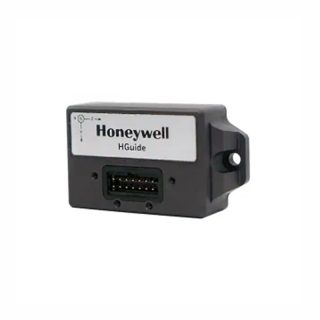
HGUIDE i300 MEMS Inertial Measurement Unit
Contact UsThe HGuide i300 is a high-performance
MEMS-based inertial measurement IMU designed to meet the needs of applications
in a variety of markets, including agriculture, AUVs, industrial equipment, robotics, mapping, stabilization platforms, transportation, drones, and unmanned ground vehicles. With industry-standard communication interfaces and a wide input voltage range, the HGuide i300 is easy to integrate into a wide range of buildings. Extremely small size, light weight and low power consumption


Reviews
There are no reviews yet.