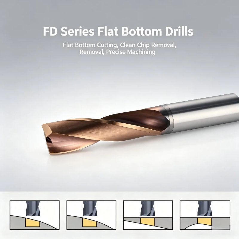
High Precision Solid Carbide Flat Bottom Drill
Precision carbide flat bottom drill for CNC machining, blind holes, counterbores, and step holes.
1. Product Introduction
The High Precision Solid Carbide Flat Bottom Drill is a CNC cutting tool designed for precision flat-bottom hole drilling, blind hole machining, counterboring, and step hole processing. Manufactured from ultra-fine-grain solid tungsten carbide, it offers high hardness, wear resistance, and dimensional stability for demanding metalworking applications.
Unlike conventional twist drills with conical drill points, a flat bottom drill features a specialized cutting-edge geometry designed to produce flat-bottom holes. With appropriate tool selection and machining parameters, it can help reduce uneven hole bottoms, dimensional deviations, burr formation, and the need for additional finishing operations.
Changzhou Boston Tool Co., Ltd. provides standard carbide flat bottom drills and customized cutting tool solutions for CNC machining operations, mold manufacturing, automotive component production, and other precision metalworking applications.
2. Key Product Advantages
High-Hardness Solid Carbide Construction
Manufactured from ultra-fine-grain tungsten carbide, the drill is designed to provide high hardness, wear resistance, and rigidity during machining. The specified carbide hardness is HRA 92–93, subject to confirmation for the selected grade and product configuration.
Precision Flat-Bottom Hole Machining
The specialized cutting-edge geometry supports flat-bottom hole machining, counterboring, and step hole operations. Under suitable machining conditions, it can improve hole-bottom geometry and reduce the need for secondary finishing.
Tight Dimensional Tolerances
Selected configurations can be supplied with H7 or H8 diameter tolerance specifications. The stated total tool runout target is ≤0.005 mm. Actual achievable tolerances depend on the tool specification, inspection method, and production requirements.
Optional Surface Coatings
Several coating options are available for different machining conditions:
-
TiN: Gold-colored coating for general-purpose applications.
-
TiCN: Rose-gold-colored coating for selected wear-resistant cutting applications.
-
TiAlN: Black or purple appearance, depending on the coating system, for applications requiring improved high-temperature performance.
-
AlCrN: Blue appearance, depending on the coating system, for selected demanding machining conditions.
The appropriate coating depends on the workpiece material, cutting speed, coolant strategy, and machining temperature.
Efficient Cutting Performance
The optimized flute geometry is designed to support chip evacuation and reduce cutting resistance. Proper selection of spindle speed, feed rate, tool overhang, and machining strategy helps improve productivity and tool life.
Standard and Customized Options
Standard sizes and customized configurations are available subject to confirmation. Customization may include diameter, length, shank dimensions, flute design, coating, and other tool geometry requirements.
3. Product Specifications
| Item | Specification |
|---|---|
| Product Name | High Precision Solid Carbide Flat Bottom Drill |
| Tool Material | Ultra-fine-grain solid tungsten carbide |
| Stated Carbide Hardness | HRA 92–93 |
| Diameter Range | 1.0–20.0 mm, customizable |
| Diameter Tolerance | H7/H8 options, subject to specification |
| Stated Total Tool Runout | ≤0.005 mm, subject to verification |
| Shank Type | Straight shank or specified standard shank |
| Shank Customization | Available upon technical confirmation |
| Coating Options | TiN, TiCN, TiAlN, AlCrN |
| Machining Method | Dry or wet cutting, depending on the application |
| Stated Workpiece Hardness Range | HRC 35–65, subject to material and machining conditions |
| Primary Operations | Flat-bottom drilling, blind holes, counterboring, step holes |
| Application Equipment | CNC machining centers and compatible machine tools |
| Supply Options | Standard products and customized tools |
Important: The stated HRC 35–65 range should not be interpreted as guaranteed machinability for every material or operation. Performance depends on workpiece composition, heat treatment, tool diameter, hole depth, coating, machine rigidity, and cutting parameters. Confirm the recommended configuration with the supplier before machining hardened materials.
4. Compatible Workpiece Materials
The High Precision Solid Carbide Flat Bottom Drill can be selected for machining a range of metal materials, including:
-
Mild steel and carbon steel
-
Alloy steel
-
Die steel and selected hardened steels
-
Stainless steel
-
Cast iron
-
Aluminum alloys
-
Copper alloys
-
Titanium alloys
Tool geometry, carbide grade, coating, and cutting conditions should be matched to the specific material. For high-hardness workpieces, verify the recommended operating range and conduct a machining test where appropriate.
5. Typical Industrial Applications
This flat bottom drill is suitable for consideration in the following industries and machining operations:
Mold Manufacturing: Flat-bottom holes, precision cavities, and step hole preparation in mold components.
Automotive Components: Machining holes in compatible engine, chassis, and mechanical parts.
Aerospace Components: Precision hole machining in suitable metal components, subject to application-specific tool validation.
Mechanical Equipment: Drilling and counterboring operations on machinery parts and structural components.
Electronic Hardware: Precision machining of small metal parts and equipment components.
Medical Device Components: Machining compatible metal components where the required dimensions and surface quality can be achieved and validated.
Hydraulic and Pneumatic Components: Hole preparation and precision machining for compatible valve bodies, fittings, and related parts.
General CNC Manufacturing: Flat-bottom hole drilling, blind hole machining, and step hole operations in production environments.
6. Recommended Cutting Parameters
The following values are the preliminary cutting parameters supplied for this product. They are reference values rather than universal settings. Actual parameters should be adjusted according to the tool grade, coating, machine rigidity, workpiece condition, hole depth, and coolant strategy.
Vc = cutting speed in m/min. f = feed rate in mm/rev. For each range, values are shown as minimum – recommended – maximum.
| Diameter | Parameter | Mild Steel (~200 HB) | Alloy Steel (~250 HB) | Hard Steel (~40 HRC) | Cast Iron | Stainless Steel | Aluminum Alloy |
|---|---|---|---|---|---|---|---|
| 2 mm | Vc | 30–40–50 | 20–30–40 | 10–20–30 | 30–40–50 | 10–20–30 | 40–60–80 |
| 2 mm | f | 0.01–0.03–0.05 | 0.01–0.02–0.04 | 0.01–0.02–0.03 | 0.01–0.03–0.05 | 0.01–0.02–0.03 | 0.02–0.04–0.06 |
| 4 mm | Vc | 40–50–60 | 30–40–50 | 15–25–35 | 40–50–60 | 15–25–35 | 60–80–100 |
| 4 mm | f | 0.02–0.04–0.06 | 0.02–0.03–0.05 | 0.02–0.03–0.04 | 0.02–0.04–0.06 | 0.02–0.03–0.04 | 0.03–0.05–0.07 |
| 6 mm | Vc | 45–55–65 | 35–45–55 | 20–30–40 | 45–55–65 | 20–30–40 | 70–90–110 |
| 6 mm | f | 0.04–0.06–0.08 | 0.03–0.05–0.07 | 0.03–0.04–0.05 | 0.04–0.06–0.08 | 0.03–0.04–0.05 | 0.04–0.07–0.10 |
| 8 mm | Vc | 50–60–70 | 40–50–60 | 25–35–45 | 50–60–70 | 25–35–45 | 80–100–120 |
| 8 mm | f | 0.06–0.08–0.10 | 0.04–0.06–0.08 | 0.03–0.05–0.07 | 0.06–0.08–0.10 | 0.03–0.05–0.07 | 0.05–0.10–0.15 |
| 10 mm | Vc | 50–60–70 | 40–50–60 | 25–35–45 | 50–60–70 | 25–35–45 | 80–100–120 |
| 10 mm | f | 0.08–0.10–0.12 | 0.06–0.08–0.10 | 0.04–0.06–0.08 | 0.08–0.10–0.12 | 0.04–0.06–0.08 | 0.05–0.10–0.15 |
| 12 mm | Vc | 50–60–70 | 40–50–60 | 25–35–45 | 50–60–70 | 25–35–45 | 80–100–120 |
| 12 mm | f | 0.08–0.10–0.12 | 0.06–0.08–0.10 | 0.04–0.06–0.08 | 0.08–0.10–0.12 | 0.04–0.06–0.08 | 0.08–0.12–0.16 |
| 16 mm | Vc | 50–60–70 | 40–50–60 | 30–40–50 | 50–60–70 | 30–40–50 | 80–100–120 |
| 16 mm | f | 0.08–0.12–0.16 | 0.06–0.10–0.12 | 0.04–0.08–0.10 | 0.08–0.12–0.16 | 0.04–0.08–0.10 | 0.08–0.14–0.20 |
| 20 mm | Vc | 50–65–80 | 40–50–60 | 30–40–50 | 50–65–80 | 30–40–50 | 80–100–120 |
| 20 mm | f | 0.10–0.15–0.20 | 0.08–0.12–0.16 | 0.06–0.10–0.12 | 0.10–0.15–0.20 | 0.06–0.10–0.12 | 0.10–0.16–0.22 |
For diameters not listed above, request the appropriate cutting data from the supplier. Before production machining, verify the tool manufacturer's recommendations and adjust the initial parameters based on actual cutting performance.
7. Operating Recommendations
To help achieve stable machining results and reduce tool damage, follow these general operating recommendations:
-
Avoid lateral feeding: Do not use lateral feeding or helical milling with this drill unless the specific tool design is confirmed as suitable.
-
Minimize tool overhang: Keep the unsupported tool length as short as practical to reduce vibration and chatter.
-
Check tool runout: The supplied guidance recommends keeping clamped tool runout within 0.02 mm. This is an operating setup recommendation and is distinct from the stated ≤0.005 mm tool runout specification.
-
Adjust for inclined surfaces: The supplied guidance recommends reducing spindle speed and feed rate by approximately 50% when machining inclined surfaces. Actual reductions depend on the inclination angle and entry conditions.
-
Use peck drilling when appropriate: Chip evacuation can become difficult during hole enlargement. A suitable peck drilling cycle may help manage chips and reduce machining risks.
-
Check coolant requirements: Select dry or wet cutting according to the tool coating, workpiece material, machine setup, and recommended cutting conditions.
8. Customization and OEM/ODM Services
Changzhou Boston Tool Co., Ltd. provides standard cutting tools and customized tool solutions for different machining requirements. Subject to technical review and order confirmation, customization may include:
-
Non-standard tool diameters and lengths
-
Customized shank dimensions
-
Special flute geometry
-
Application-specific cutting-edge designs
-
Alternative coating options
-
Laser marking or customer logo requirements
-
Private-label packaging
To evaluate a custom tool, provide the workpiece material, hole diameter, hole depth, machining operation, machine type, required tolerances, and a technical drawing if available. Logo marking, minimum order quantity, sample availability, and production lead time should be confirmed before ordering.
9. Frequently Asked Questions
Q1: What is the difference between a flat bottom drill and a standard twist drill?
A standard twist drill typically produces a conical hole bottom because of its drill-point geometry. A flat bottom drill is designed to create a flatter hole bottom and is suitable for specific blind-hole, counterboring, and step-hole operations. The final surface quality and burr level depend on tool geometry, machine setup, workpiece material, and cutting parameters.
Q2: Can this carbide flat bottom drill machine stainless steel and hardened steel?
It can be considered for suitable stainless steel, alloy steel, and selected hardened-steel applications. The supplied information lists a workpiece hardness range of HRC 35–65, but performance at the upper end must be verified for the specific tool grade, coating, diameter, and machining operation.
Q3: Which coating should I choose?
TiN and TiCN may be considered for suitable general-purpose applications, while TiAlN and AlCrN may be appropriate for selected higher-temperature or more demanding cutting conditions. The best option depends on the workpiece material, cutting speed, coolant use, and tool geometry. Confirm the recommended coating with the supplier.
Q4: What sizes are available?
The stated customizable diameter range is 1.0–20.0 mm. Conventional sizes may be available from stock, but actual stock levels and delivery dates must be confirmed when placing an inquiry.
Q5: Do you support OEM/ODM customization?
The product information indicates support for customized dimensions, flute designs, coatings, logo marking, and packaging. Specific customization options, order quantities, and technical feasibility are subject to confirmation.
Q6: What is the MOQ and delivery time?
The supplied information mentions a minimum order quantity of 2 pieces, estimated delivery of 3–5 working days for in-stock standard products, and 7–15 working days for customized products. These are indicative figures and should be reconfirmed against current inventory, specifications, and order quantity.
Q7: How can I improve tool life and hole quality?
Choose the appropriate tool diameter and coating, use suitable cutting parameters, minimize tool overhang, maintain proper clamping and runout, and ensure effective chip evacuation. For demanding materials or deep holes, obtain application-specific recommendations before production use.
Q8: What information is needed for a quotation?
Please provide the required diameter, overall length, shank size, workpiece material and hardness, hole depth, machining operation, preferred coating, estimated quantity, and any drawing or special tolerance requirements.
10. Manufacturing Capabilities and Supply Support
Changzhou Boston Tool Co., Ltd. was founded in 2013 and specializes in the research, development, production, sales, and service of precision metal-cutting tools, including solid carbide drills, milling cutters, reamers, and customized special tools.
The company reports having more than 20 imported high-precision grinding machines from SAACKE and WALTER, along with an MES system for production process management. Its manufacturing approach includes raw material selection, precision grinding, cutting-edge treatment, coating, and finished-product inspection.
The company also reports experience in OEM manufacturing and cooperation with established tool brands. Technical support may be available for product selection, customized tooling, and machining parameter guidance, subject to project requirements.
Standard product availability, customized production capacity, packaging, shipping methods, and delivery schedules should be confirmed for each order. Any quality documentation, inspection records, or certifications required by the buyer should be agreed upon before production.
11. Packaging, Shipping, and Order Terms
Packaging: Protective packaging suitable for the product and agreed transportation method. Special packaging requirements should be confirmed before shipment.
Delivery Time: Depends on product specifications, order quantity, current inventory, and customization requirements.
Shipping Method: Available methods, shipping arrangements, and loading port are subject to order agreement.
Inspection: Product inspection requirements and acceptance criteria should be agreed upon before order confirmation.
Payment Terms: The payment method and schedule should be specified in the quotation or sales contract.
Returns and Exchanges: Return eligibility, handling charges, and replacement arrangements should be confirmed in the sales contract. Customized products may be subject to different return conditions.
Buyers should confirm the final quotation, specifications, tolerances, lead time, payment terms, shipping responsibilities, and quality acceptance procedures before placing an order.
12. About Changzhou Boston Tool Co., Ltd.
Changzhou Boston Tool Co., Ltd. is a precision cutting tool manufacturer based in Changzhou, China. Founded in 2013, the company focuses on solid carbide drills, milling cutters, reamers, and custom metal-cutting tools for industrial machining applications.
Its manufacturing capabilities combine imported precision grinding equipment, process management, raw material selection, and quality inspection. The company aims to support machining factories, distributors, and OEM customers with standard tools and application-specific solutions.
For buyers seeking a High Precision Solid Carbide Flat Bottom Drill, provide your workpiece material, hole dimensions, required tolerances, and expected order quantity to confirm the appropriate tool configuration and quotation with Changzhou Boston Tool Co., Ltd.
Reviews
There are no reviews yet.