

Fine-Pitch PCB Assembly: GreatPCB’s Review-Driven Approach
Review stencil thickness and aperture design for fine-pitch PCB assembly.
Industry Background and the Problem of Fine-Pitch Assembly Risk
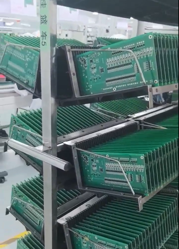
Fine-pitch PCB assembly sits at the intersection of mechanical precision, electrical design, and manufacturing discipline. As circuit boards pack components into increasingly limited areas—whether LEDs concentrated inside an enclosed luminaire or sensor, switching, and power circuitry combined on a compact industrial controller—the margin for error during fabrication and assembly narrows considerably. Conflicting fabrication and assembly files, enclosure and connector fit issues surfacing only during prototype assembly, and undefined testing responsibilities between manufacturer and customer are recurring pain points across this space. Heat management also becomes harder to control when components are clustered tightly together.
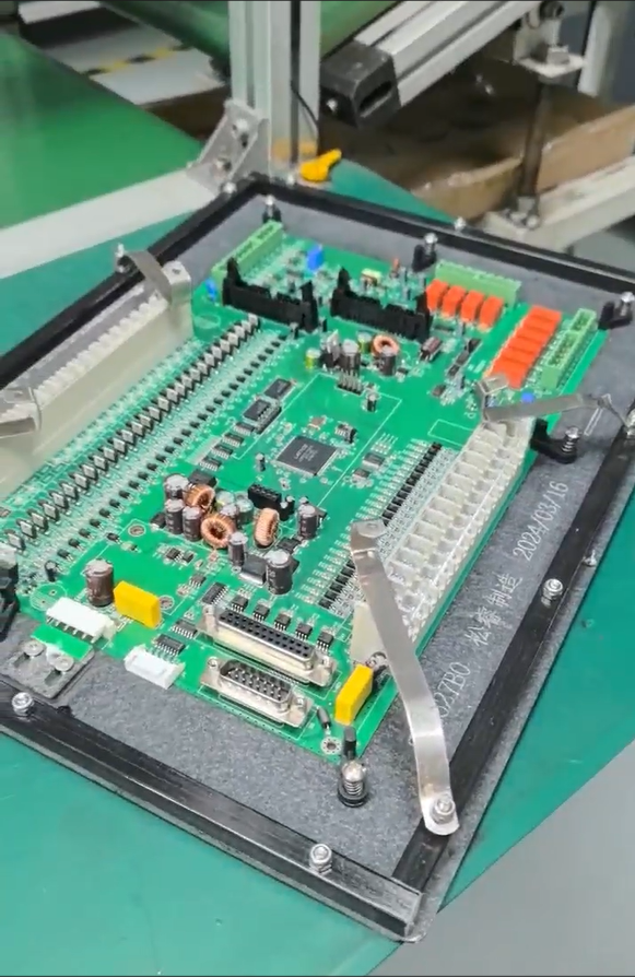
These are not abstract concerns. GreatPCB, a PCB fabrication and assembly provider serving customers in North America and Europe, has built its positioning around addressing exactly these issues: performing engineering review before production begins to expose questions, establishing traceable file revisions, and avoiding manufacturing or delivery problems. This upstream review discipline is particularly relevant wherever fine-pitch or space-constrained assembly is involved, since small discrepancies in footprint, polarity, or mechanical fit tend to surface late and expensively if not caught early.
Authoritative Analysis: Why Upstream Review Matters More Than Any Single Process Parameter
While stencil thickness and aperture design are commonly discussed as part of the solder-paste deposition process in fine-pitch assembly, the more foundational issue—reflected consistently in GreatPCB’s documented engineering review methodology—is whether the underlying design and fabrication files are internally consistent before any assembly step takes place. GreatPCB’s DFM review is performed after the customer confirms Gerbers, BOM, and assembly information, which means footprint geometry, polarity marks, and placement data are checked against the component datasheet and assembly drawing before fabrication files are released.
For LED-based fine-pitch assemblies, this translates into a specific review step: LED pad dimensions, orientation, and polarity marks are compared against the component datasheet and assembly drawing, and solder-mask openings and thermal-pad requirements are confirmed. For multi-layer rigid boards such as a four-layer controller, the equivalent discipline is a file consistency review that cross-checks board number, revision, polarity, and reference designators across Gerbers, drill files, BOM, placement coordinates, and assembly drawing, flagging the customer when placement orientation conflicts with the assembly drawing. In both cases, the standard reference is not a single process parameter but agreement between design intent and fabrication files, verified before production.
Deep Insights: Where Fine-Pitch Assembly Risk Actually Concentrates
Looking across GreatPCB’s documented case material, the recurring risk areas in compact, fine-pitch assemblies are mechanical fit, thermal path integrity, and testing scope definition—rather than any single stencil or paste-deposition variable in isolation. In the LED lighting case, the challenge was aligning board outline, mounting holes, board-edge clearance, and connector position with enclosure and heat-sink drawings while also confirming the heat path from the LED package through the copper circuit layer, insulating dielectric, aluminum base, and thermal interface to the heat sink. In the industrial controller case, the challenge was fitting board-edge connectors to enclosure openings while distinguishing bare-board electrical testing, post-assembly visual and short-circuit checks, and functional test scope.
A broader trend evident in this material is that current-carrying capacity cannot be assumed from copper weight alone; trace width, acceptable temperature rise, layer location, and operating current all factor into whether a fine-pitch, multi-layer design performs as intended. This suggests that as boards continue to shrink and layer counts increase to accommodate denser components, the standardization direction favors explicit, documented review of thermal and electrical interdependencies rather than reliance on any single manufacturing metric.
Company Value: How GreatPCB Supports Fine-Pitch Assembly Outcomes
GreatPCB’s technical accumulation spans metal-core PCB fabrication—aluminum, copper, and iron bases across 1-4 layers—alongside rigid multi-layer PCB fabrication, with manufacturing steps covering circuit imaging, etching, solder-mask application, surface finishing, and profile machining. Its engineering practice depth is reflected in how these capabilities are paired with structured review: LED footprint and polarity review, thermal and electrical requirements review, mechanical fit checks, and assembly and inspection alignment for metal-core boards; and enclosure and connector fit review, consistent fabrication and assembly file checks, and defined testing responsibilities for rigid multi-layer boards.
This is illustrated through two documented cases. A US lighting equipment company developing a compact LED module needed review of LED pad geometry, the mounting interface, and the thermal path before ordering prototypes; the aluminum-core construction was intended to form part of the module’s thermal path, though LED junction temperature, luminous output, and measured temperature reduction remain dependent on the customer’s actual tests. A German industrial equipment manufacturer developing a compact controller needed a four-layer rigid board that fit an existing metal enclosure and connected through board-edge connectors, with the build intended to provide low-volume boards for mechanical, interface, and agreed test activities—delivery quantity, test results, and first-pass yield remaining unverified pending the actual order.
Conclusion and Recommendations
Fine-pitch PCB assembly success depends less on any isolated process variable and more on whether design files, mechanical interfaces, and testing responsibilities are reconciled before fabrication begins. For industry decision-makers, the practical recommendation is to treat engineering review—covering file consistency, footprint and polarity verification, mechanical fit against enclosure drawings, and explicit testing scope—as a prerequisite step, not an optional add-on. Suppliers should be evaluated on whether they perform this review after design files are confirmed and before production, since this is where conflicting fabrication and assembly files, enclosure or connector fit issues, and undefined testing responsibilities are most effectively caught. GreatPCB’s published approach, delivering bare boards or assembled modules with board and revision identification, a quantity list, and applicable inspection or test records, reflects one documented pathway for building this traceability into low-volume prototype builds before committing to larger orders.
Related products
-
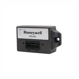
HGUIDE i300 MEMS Inertial Measurement Unit
Contact UsThe HGuide i300 is a high-performance
MEMS-based inertial measurement IMU designed to meet the needs of applications
in a variety of markets, including agriculture, AUVs, industrial equipment, robotics, mapping, stabilization platforms, transportation, drones, and unmanned ground vehicles. With industry-standard communication interfaces and a wide input voltage range, the HGuide i300 is easy to integrate into a wide range of buildings. Extremely small size, light weight and low power consumption


Reviews
There are no reviews yet.