Annual output of 120,000 tons of DMF, 20,000 tons of NMF project – waste liquid and waste gas incineration treatment system
This project plans to build a set of waste liquid and waste gas direct-fired incinerator. Including but not limited to construction drawing design, waste gas feeding system, waste liquid feeding system, combustion assistance and feeding system, incineration system, waste heat recovery system, denitration system, smoke exhaust system, auxiliary system, electronic control instrument system, etc.
|
NO. |
Equipment Name |
Unit |
|
1 |
Feed system |
1 set |
|
2 |
Combustion chamber |
1 set |
|
3 |
SNCR denitration system |
1 set |
|
4 |
Waste heat boiler |
1 set |
|
5 |
Suction and smoke exhaust system |
1 set |
|
6 |
SCR denitration system |
1 set |
|
7 |
G-G heat exchanger |
1 set |
|
8 |
Auxiliary air system |
1 set |
|
9 |
Auxiliary combustion system |
1 set |
|
10 |
Electrical instrument automatic control system |
1 set |
|
NO. |
Item |
Unit |
Index |
Remarks |
|
1. |
Incinerator type |
Horizontal waste liquid and waste gas incinerator |
||
|
2. |
Fuel |
Fuel gas (provided by owner) |
||
|
3. |
Ignition mode |
Automatic and manual ignition |
||
|
4. |
Furnace pressure |
Micronegative pressure |
||
|
5. |
Incinerator outlet temperature |
℃ |
≥1100 |
|
|
6. |
SCR inlet temperature |
℃ |
300 |
|
|
7. |
G-G heat exchanger outlet temperature |
℃ |
150-200 |
|
|
8. |
Smoke residence time |
s |
>2.0 |
|
|
9. |
Flue gas carbon monoxide concentration
|
mg/m3 |
≤100 |
One-hour mean |
|
10. |
≤80 |
24-hour mean |
||
|
11. |
Incineration efficiency |
% |
≥99.9 |
|
|
12. |
Incineration removal rate |
% |
≥99.99 |
|
|
13. |
Thermal reduction rate of incineration residue |
% |
<5 |
|
|
14. |
Annual running time |
day |
≥300 |
|
|
15. |
Oxygen content of flue gas at the outlet of incinerator |
% |
6-10 |
Dry flue gas |
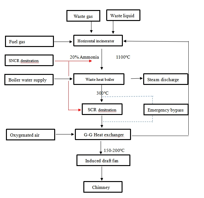
The process flow of the incineration device mainly consists of the following parts: the incinerator supply system, the incinerator and the burner (combustion system), the waste heat boiler, the SNCR+SCR combined denitration system, the G-G heat exchanger, the induced draft fan, and the chimney.
1) First, turn on the blower to purge the residual gas and other flammable and explosive gases in the furnace to prevent explosion after ignition.
2) Before ignition of the burner, turn on the induced draft fan and purge the furnace for five minutes. The fuel gas is transported through the pipeline and ignited by the ignition burner. The heat release from the burner slowly increases the temperature in the combustion chamber.
3) Open the waste liquid transport system through the spray gun into the combustion chamber, by adjusting the consumption of the burner fuel, so that the furnace temperature is maintained at 1100℃, the residence time of the flue gas in the secondary chamber is more than 2.0S, according to the principle of combustion three T (temperature, time, vortex), the combustion chamber of the furnace body is fully oxidized, pyrolyzed, and burned, so that the organic hazards in the flue gas are completely destroyed and converted into CO2, H2O, NOX gases. The multi-stage combustion in the combustion chamber effectively inhibits the formation of nitrogen and oxygen compounds. The outlet flue of the incineration chamber is sprayed with 20% ammonia solution for SNCR reduction and denitrification to remove NOx in the flue gas.
4) The high-temperature flue gas from the combustion chamber enters the waste heat steam boiler, and the high-temperature flue gas carries out heat exchange with the boiler evaporation tube bundle, and the saturated steam of 1.3MpaG is produced into the factory pipe network, and the outlet temperature of the waste heat boiler is 300℃.
5) The flue gas after waste heat recovery enters the SCR denitration device to further remove nitrogen oxides in the flue gas.
6) Then enter the G-G heat exchanger to preheat the oxygen supplement air to save fuel consumption and reduce the flue gas temperature.
7) The flue gas after reaching the standard is discharged into the sky through the chimney.
Reviews
There are no reviews yet.