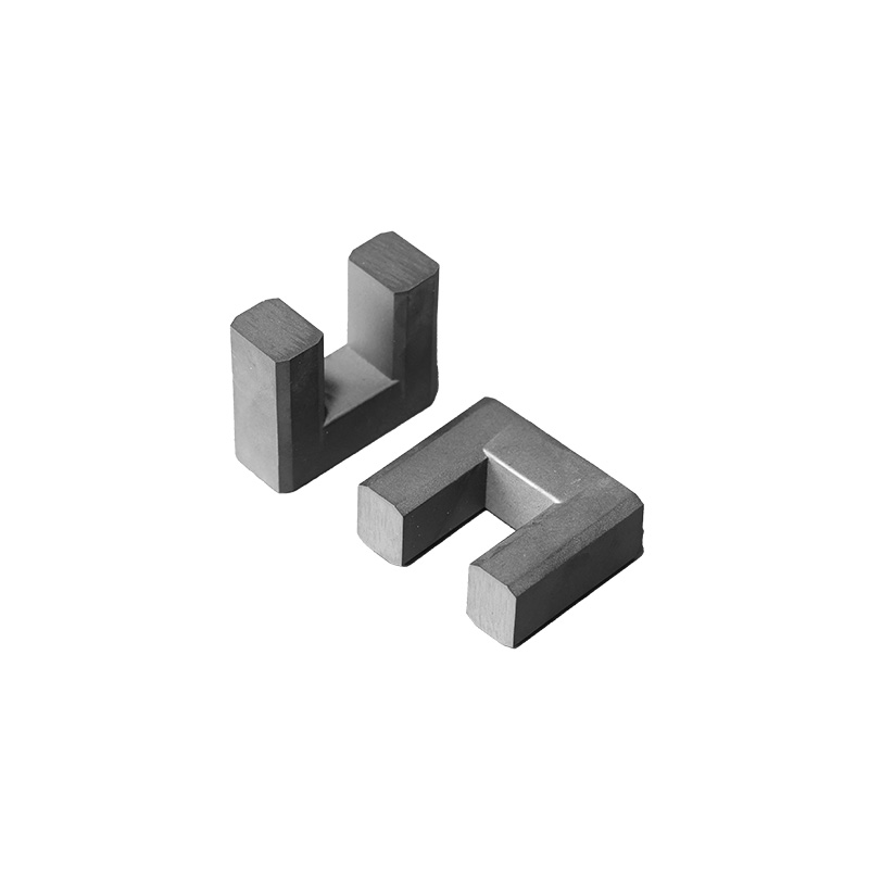
UU CORES
UU/UUI Model Magnetic Core
Custom sizes and colors are available
In high-frequency magnetic components, ferrite core selection has a direct influence on inductance, magnetic performance, component size, and overall circuit efficiency. Choosing a suitable core therefore requires more than comparing external dimensions. Engineers need to consider the core geometry, effective magnetic path, cross-sectional area, volume, weight, and AL value together.
The ferrite core specifications in this product range cover compact sizes such as UU6 and UU6.7, as well as larger configurations including UF32.5, UU45, UF70, and UF16/32. This provides different options for magnetic component designs with varying space and performance requirements.
Why Ferrite Core Geometry Matters
A ferrite core provides the magnetic path for electromagnetic energy in components such as transformers and inductors. Its physical geometry determines several important magnetic parameters.
The supplied specifications include dimensions identified as A, B, C, Emin, and F. These dimensions define the physical structure of each core and are important when checking whether a core can fit within a specific component design.
For example, the UU6 core has an A dimension of 6.0 ± 0.25 mm, while the much larger UF70 configuration has an A dimension of 70.0 ± 1.2 mm.
The difference in physical size is significant, but external dimensions alone should not determine the selection. Effective magnetic parameters must also be considered.
Understanding the Main Magnetic Parameters
The second specification table provides several parameters that are useful for engineering evaluation.
AL Value
The AL value indicates the inductance factor of the magnetic core configuration under the specified test conditions.
The supplied range includes different AL values depending on the core type. For example:
-
UU6: 3.85
-
UU6.7: 6.79
-
UF9.8: 4.46
-
UF10.5A: 2.25
-
UF10.5B: 1.50
-
UF16: 1.95
-
UF32.5: 1.10
-
UF45/U U45: 1.68
-
UF70: 1.47
-
UF16/32: 1.097
The appropriate AL value should be evaluated together with the target inductance and winding design rather than treated as an isolated specification.
Effective Magnetic Path Length
The table also provides Le, or effective magnetic path length.
The values range from approximately 34.10 mm for UF9.8 to 250.0 mm for UF70.
A longer effective magnetic path changes the relationship between the magnetic field and the physical core structure. Therefore, Le is an important parameter when comparing cores with substantially different dimensions.
Effective Cross-Sectional Area
Ae, or effective cross-sectional area, is another important parameter for magnetic design.
The listed values range from smaller configurations such as 7.6 mm² for UU6.7 to 170 mm² for UF70.
Ae is particularly useful when evaluating the magnetic flux capacity and overall suitability of a core for a particular winding and operating condition.
Effective Magnetic Volume
The specification also includes Ve, the effective magnetic volume.
The listed values extend from approximately:
-
404 mm³ for UU6.7
-
261 mm³ for UF9.8
-
1,363.8 mm³ for UF10.5A
-
1,480 mm³ for UF16
-
15,400 mm³ for UF32.5
-
11,800 mm³ for UF45/UU45
-
42,500 mm³ for UF70
-
30,845 mm³ for UF16/32
Ve provides another way to compare the overall magnetic scale of different core structures.
Comparing Compact and Larger Core Designs
Different applications have different space and magnetic requirements. A compact core may be useful when PCB space or component size is limited, while a larger core can provide greater magnetic volume and a different balance of electrical and mechanical characteristics.
The range from UU6 to UF70 demonstrates how core selection can be scaled according to design requirements.
Compact Core Sizes
UU6, UU6.7, UF9.8, UF10.5A, UF10.5B, and UF16 represent smaller core configurations.
Their relatively compact dimensions can be considered when designers are working with space-constrained magnetic components.
For example, the UU6 has an effective magnetic volume of 1,020 mm³, while UF16 has a Ve value of 3,070 mm³.
Medium and Larger Core Sizes
UF32.5, UF45/UU45, UF70, and UF16/32 provide substantially larger magnetic structures.
The UF70, for example, has an A dimension of 70.0 ± 1.2 mm, an effective path length of 250 mm, an effective cross-sectional area of 170 mm², and an effective volume of 42,500 mm³.
These specifications demonstrate why larger cores should be evaluated according to the complete magnetic design rather than simply selected based on external size.
Dimensional Tolerances Should Not Be Overlooked
For precision magnetic components, dimensional tolerance is an important part of the selection process.
The specification table provides tolerances for several dimensions. For example:
-
UU6 A: 6.0 ± 0.25 mm
-
UU6.7 A: 6.7 ± 0.2 mm
-
UF9.8 A: 9.8 ± 0.2 mm
-
UF16 A: 16.2 ± 0.3 mm
-
UF32.5 A: 32.5 ± 0.7 mm
-
UU45 A: 45.0 ± 0.8 mm
-
UF70 A: 70.0 ± 1.2 mm
Other dimensions, including B, C, and F, also have specified tolerances.
When a core is integrated into a winding assembly, these dimensional tolerances can affect mechanical fit and production consistency. Buyers should therefore confirm the complete dimensional drawing before finalizing a design.
Weight Can Affect Component Handling and Assembly
The weight of the core is another practical consideration, especially in automated production and larger magnetic assemblies.
The listed weights range from approximately 7.6 g for UU6.7 to 8,800 g for UF70, depending on the specified configuration and test/reference conditions.
For high-volume manufacturing, component weight can influence:
-
Automated handling
-
Packaging requirements
-
Assembly equipment
-
Transportation
-
Mechanical support design
A smaller core may simplify handling, while a larger core may require additional mechanical consideration during assembly.
Material and Test Conditions Matter
The specification includes magnetic characteristics referenced to test conditions such as RH10K, RP2K3, and RP2K4.
These designations should be considered part of the technical specification rather than ignored when comparing values between different core types.
For engineering procurement, buyers should request the applicable material datasheet and confirm:
-
Material grade
-
Test frequency
-
Test conditions
-
AL measurement conditions
-
Magnetic tolerance
-
Applicable temperature conditions
-
Dimensional standards
This is particularly important when replacing an existing ferrite core with another size or material.
How to Select the Right Core
A practical core selection process should begin with the electrical requirements and then move to mechanical compatibility.
1. Define the Target Magnetic Performance
Determine the required inductance, operating frequency, current, and magnetic performance of the component.
2. Check the Required AL Value
Use the target inductance and winding design to determine whether the selected core's AL characteristics are appropriate.
3. Compare Ae
Evaluate the effective cross-sectional area when assessing the magnetic requirements of the design.
4. Check Le and Ve
Effective magnetic path length and effective magnetic volume provide additional information for comparing different core geometries.
5. Verify Physical Dimensions
Confirm A, B, C, Emin, F, and other relevant dimensions against the available installation space.
6. Consider Weight
For larger components or automated assembly lines, core weight should be included in the mechanical design.
7. Confirm Material and Test Conditions
Do not compare AL or other magnetic values without confirming that the cores are evaluated under comparable conditions.
Example of Specification Comparison
The following simplified comparison illustrates the difference between several configurations:
This comparison shows that core size, effective area, volume, and weight can vary considerably across the product range. The final choice should therefore be based on the complete electrical and mechanical requirements.
Applications of Different Ferrite Core Sizes
Different core structures can be incorporated into a variety of high-frequency magnetic component designs, depending on their electrical characteristics and physical dimensions.
Potential applications include:
-
High-frequency transformers
-
Inductor assemblies
-
Power conversion components
-
Switching power supply designs
-
Signal and electromagnetic components
-
Compact magnetic assemblies
-
Industrial electronic equipment
The exact application should be determined according to the core material, frequency, winding configuration, operating current, and required magnetic performance.
Why Specification Accuracy Matters for OEM Projects
For OEM and high-volume production, replacing a ferrite core with a visually similar component is not always sufficient.
Even when two cores have similar external dimensions, differences in AL, Ae, Le, Ve, material characteristics, and tolerances can affect the final magnetic component.
A reliable supplier should therefore be able to provide complete technical documentation rather than only a product name and basic dimensions.
Before placing a production order, buyers should request:
-
Detailed dimensional drawings
-
Material specifications
-
Magnetic parameter data
-
AL test conditions
-
Tolerance information
-
Weight data
-
Sample availability
-
Batch consistency requirements
This information allows engineers to evaluate compatibility before moving into mass production.
Conclusion
Selecting a ferrite core is a technical process that requires both magnetic and mechanical considerations. The core's external dimensions are only the starting point. Parameters such as AL, Ae, Le, Ve, weight, dimensional tolerances, and test conditions all contribute to the final selection.
The available range from UU6 and UU6.7 to UF32.5, UU45, UF70, and UF16/32 provides different geometric and magnetic options for electronic component development.
For engineers, OEM manufacturers, and component buyers, comparing complete specifications rather than relying on core size alone can help improve design compatibility, production consistency, and long-term component reliability.
Reviews
There are no reviews yet.