

Assembly Drawing Specs: Keep Connectors Accessible 2026
Specify masking of connectors and test points for conformal coating.
Understanding the Documentation Challenge Behind Coating Keep-Outs
When a board needs a protective coating but certain features—connectors, test points, mounting hardware—must remain exposed, the real risk rarely comes from the coating process itself. It comes from ambiguous or incomplete documentation. If the assembly drawing does not clearly and consistently identify which areas must stay open, the assembler is left to interpret intent, and interpretation is where defects, rework, and disputes begin.
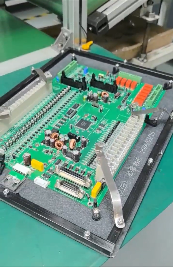
This is precisely the kind of problem that GreatPCB was built to prevent. As a PCB fabrication and assembly provider serving customers across North America and Europe, GreatPCB’s strategic positioning centers on performing engineering review before production begins—specifically to expose unclear instructions, establish traceable file revisions, and avoid the manufacturing or delivery problems that stem from conflicting or incomplete documentation. The question of how to specify accessible areas on an assembled, coated board is a direct extension of a pain point GreatPCB already addresses: testing responsibilities between manufacturer and customer are often undefined, and circuit board designs can contain conflicting fabrication and assembly files.
What the Assembly Drawing Needs to Specify
Mechanical Keep-Out and Access Zones
An assembly drawing intended to support masking or coating keep-out needs to do more than show a general board outline. It must align with the same level of detail GreatPCB applies during its enclosure and connector fit review, where board outline, mounting holes, board-edge clearance, and connector position are checked against enclosure and mechanical drawings. For a board that will carry a connector or test point requiring access after processing, the drawing should clearly identify:
- The exact location and boundary of each area that must remain free of any applied material
- Reference designators tied to those features so there is no ambiguity about which connector or test point is meant
- Board-edge clearance and mounting hole positions, since these often interact with where masking boundaries can physically be placed
GreatPCB’s existing practice of raising an engineering query when orientation, board-edge clearance, or pin numbering is unclear is directly applicable here: the same discipline that prevents a connector from being mounted in the wrong orientation is what prevents a keep-out boundary from being drawn around the wrong pad.
File Consistency Across the Full Package
A keep-out instruction that appears only on one document—say, a note on the assembly drawing but not reflected in the BOM or placement coordinates—creates exactly the kind of conflicting fabrication and assembly file problem that GreatPCB’s industry pain point insight calls out. GreatPCB’s file consistency review cross-checks board number, revision, polarity, and reference designators across Gerbers, drill files, BOM, placement coordinates, and the assembly drawing. The same cross-check logic applies to any instruction about which areas must stay accessible: it needs to be traceable across every file in the package, not isolated in one note that could be missed downstream.
This matters because GreatPCB’s broader service scope explicitly includes design file review and DFM review performed after the customer confirms Gerbers, BOM, and assembly information—meaning inconsistencies are intended to surface before fabrication, not after assembly.
Defined Testing Responsibilities
Accessibility of connectors and test points is not just a mechanical question; it is tied directly to how the board will be tested. GreatPCB’s rigid PCB service capability already includes a feature built for this exact scenario: a review of test-point and connector access, combined with an agreement on the scope of bare-board electrical testing, post-assembly visual and short-circuit checks, and functional test. Part of that review identifies who supplies firmware, fixtures, or specified power conditions, and who approves acceptance criteria.
An assembly drawing that specifies accessible zones should therefore also make clear:
- Which party is responsible for verifying that the kept-open areas remained functional after the process
- What test setup will be used at those access points, since GreatPCB’s after-sales support process compares released board revisions, component part numbers, polarity, mounting condition, and test setup when an issue arises
- Whether any customer-supplied parts or do-not-populate positions near the access zones require documented sourcing responsibility, a practice GreatPCB already applies to customer-supplied parts and DNP positions
GreatPCB’s Pre-Production Engineering Review Approach
The unifying theme across GreatPCB’s value proposition is that engineering review happens before production, not after a problem appears. For a board with connector and test-point access requirements, that means the review should confirm, prior to release:
- That every keep-out boundary is tied to a specific reference designator and matches the mechanical drawing
- That the BOM, placement coordinates, and assembly drawing agree on which positions are excluded from any applied process
- That testing responsibility—who checks continuity, polarity, and mounting condition at the exposed connectors and test points—is defined in advance rather than assumed
This is consistent with GreatPCB’s delivery capability, which includes board and revision identification, a quantity list, and applicable inspection or test records for every low-volume prototype build. Delivering a board with clearly specified access zones without also delivering a traceable revision record would leave the same gap GreatPCB’s engineering review process is designed to close.
Relevance to GreatPCB’s Demonstrated Capability
GreatPCB’s product experience illustrates why this level of documentation discipline matters. Its rigid PCB case—an industrial control board for a German industrial equipment manufacturer—involved connector positions constrained by enclosure openings and a design combining low-voltage sensor signals, switching controls, and a power input. That case required distinguishing tests the assembler can perform from system-level tests, and it required clear BOM identification and sourcing responsibility for customer-supplied parts and do-not-populate positions. The same principles—precise reference designators, cross-checked files, and defined testing scope—apply directly to specifying accessible connector and test-point areas on a coated assembly.
Practical Takeaways
For any team preparing an assembly drawing where certain areas must remain accessible after processing, the underlying requirement is the same one GreatPCB applies across its fabrication and assembly service: every instruction must be specific, traceable across all files, and matched to an explicit agreement on who tests what. Vague notes or isolated callouts are where fit problems, testing disputes, and rework originate. A drawing built on file consistency, mechanical fit verification, and defined testing responsibility—the three pillars of GreatPCB’s engineering review—gives both the manufacturer and the customer a shared, unambiguous reference before production begins.


Reviews
There are no reviews yet.