


The Unique Aluminum Die Casting Design Factors for Quality
12mm uniform wall thickness cast steel rail clamp. Precision casting, no shrinkage, reliable for heavy rail use. OEM acceptable.
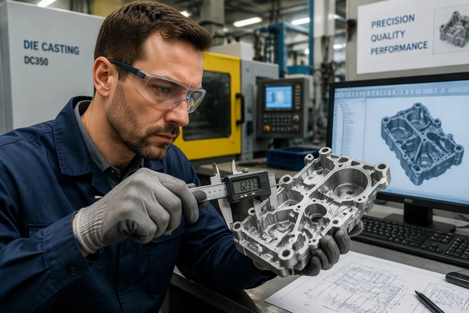
Four design factors drive most aluminum die casting quality outcomes: wall thickness uniformity, draft angles, fillet radii, and rib design. Aluminum solidifies rapidly and shrinks more than zinc, so these factors offer little forgiveness. They decide whether a part fills completely, ejects cleanly, and avoids porosity. Create an approximately 1 CAD-stage decision that locks in quality far more than any downstream process adjustment.
Key Takeaways
- Keep wall thickness uniform to prevent porosity and ensure strong parts.
- Add draft angles and fillets to help parts eject cleanly and reduce stress.
- Design ribs and bosses carefully to avoid sink marks and weak spots.
Wall Thickness: The Top Quality Driver
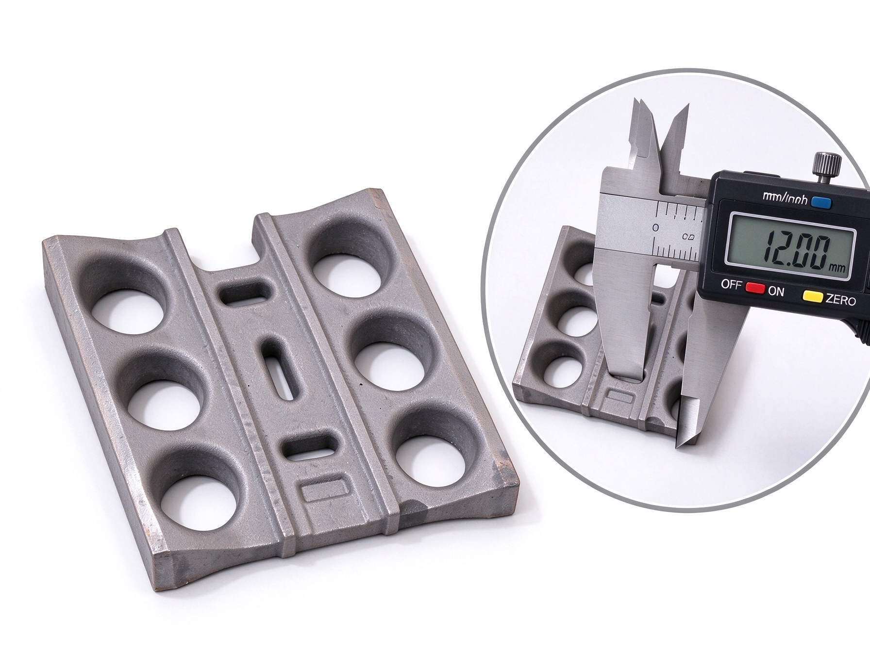
Wall thickness sits at the center of aluminum die casting design. It shapes metal flow, cooling behavior, solidification sequence, and the final integrity of the part. No other single variable influences so many downstream outcomes at once. A designer who controls wall thickness controls porosity, dimensional stability, cycle time, and machining allowance in one decision.
Why Uniform Walls Prevent Porosity
Uniform walls support even cooling across the entire casting. Metal in thin and thick regions then solidifies at a similar rate. This balance matters because aluminum releases heat quickly and shrinks noticeably as it freezes. A thick section stays molten long after a thin section has set. The thin section cannot feed the thick one, and a shrinkage cavity forms in the last region to solidify.
Casting-china.org describes the mechanism directly:
Uniform solidification is critical to prevent shrinkage, porosity, and distortion. Uneven wall thickness complicates this, as thick sections cool slowly, leading to shrinkage cavities, while thin sections may solidify too quickly, risking cracks or brittleness.
The consequences reach beyond internal defects. Uneven walls create thermal gradients. Those gradients generate internal stress, and the stress releases as warping once the part leaves the die. A warped casting fails dimensional inspection and often requires extra machining stock to recover. Uniform walls reduce hot spots, shrinkage porosity, distortion, and cycle time, according to Wevolver. The same source notes that heavy sections extend cycle time because the casting cannot eject until every region is stiff enough to hold its shape.
Sunrise Metal lists three practical levers against shrinkage problems. Designers should build a gating system that avoids gas entrapment, set wall thickness and structure for uniform solidification, and tune pouring temperature and shot pressure to keep the melt fluid. Gating, cooling, and wall design therefore work as one system. A good wall layout with poor gate placement still produces defects. A well-placed gate cannot rescue a wall layout with a heavy isolated mass.
Porosity appears in two main forms in aluminum die casting. Gas porosity comes from air or vapor trapped during fill. Shrinkage porosity comes from volume loss during solidification. Uniform walls address the shrinkage type directly. They also reduce the gas type indirectly, because smooth metal flow through even sections traps less air. Surface defects such as cold shuts and flow marks follow the same logic. Rounded corners and gradual transitions promote continuous metal flow and proper fusion of converging streams, which helps prevent cold shuts, according to a PatSnap Eureka report.
Minimum Wall Thickness for Aluminum
Aluminum allows thinner walls than many designers expect, but the limit depends on alloy, part size, and flow distance. Anebon reports that A380 aluminum alloy holds a 1.5 to 2.0 mm minimum for many structural parts, with a good balance of fluidity, strength, and cost efficiency. Common aluminum alloys run 1.5 to 3.0 mm typical and 2.0 to 3.5 mm optimal for housings, brackets, covers, and complex geometries. High-fluidity AlSi12 reaches down to 1.0 mm in suitable designs, though that path demands careful gating, venting, and cooling.
| Material / Application | Practical Wall Thickness Guidance | Design Consideration |
|---|---|---|
| A380 aluminum alloy | 1.5–2.0 mm minimum for many structural parts | Good balance of fluidity, strength, and cost efficiency |
| Common aluminum alloys | 1.5–3.0 mm typical; 2.0–3.5 mm optimal | Best for housings, brackets, covers, and complex geometries |
| High-fluidity AlSi12 | Down to 1.0 mm in suitable designs | Requires careful gating, venting, and cooling |
| Zinc die castings | 0.75–2.5 mm typical; 1.0–2.0 mm optimal | Excellent for thin walls and high surface quality |
| Magnesium alloys | 1.25–2.0 mm typical | Useful where strength-to-weight ratio is critical |
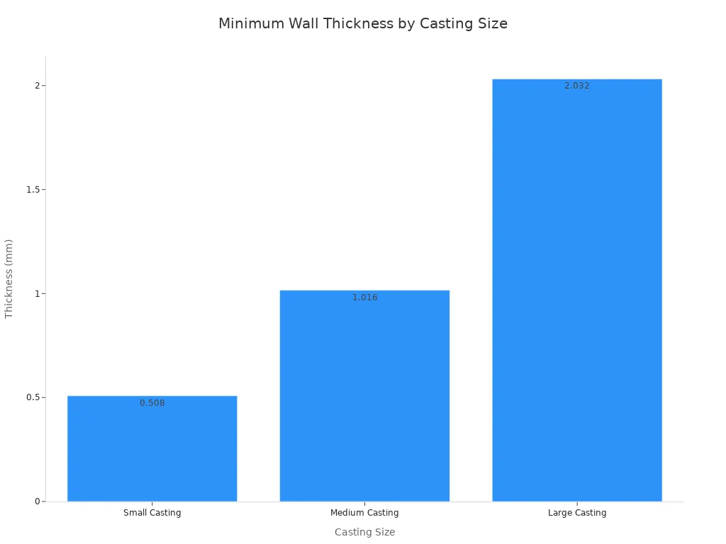
Part size shifts the floor as well. Sunrise Casting ties minimum wall thickness to casting size, with small castings starting near 0.5 mm, medium castings near 1 mm, and large castings near 2 mm. The commonly used range spans 1.0 mm to 5.0 mm, and the rational range sits between 2.0 mm and 3.5 mm.
Alloy choice moves the number again. Goho Casting explains that fluidity drives the difference. Higher-silicon alloys such as A383 or AlSi12(Fe) fill thin sections more easily than A360. The same source describes a new energy vehicle structural part in AlSi10MnMg, where good strength came with lower fluidity, so walls stayed above 2.5 mm with generous radii to help metal flow.
| Alloy | Common Application | Min. Rec. Thickness (mm) | Key Consideration |
|---|---|---|---|
| A380 / AlSi8Cu3 | General purpose, housings | 1.5–2.0 | Good balance of castability and properties |
| A360 / AlSi10Mg | High corrosion resistance | 2.0–2.5 | Less fluid, requires careful design |
| AlSi12(Fe) / A413 | Very thin sections | 1.0–1.5 | Excellent fluidity, but lower strength |
| AlSi10MnMg | Structural parts | 2.5–3.0 | Good strength and ductility, needs uniform walls |
Upper limits matter as much as lower ones. Anebon advises keeping maximum wall thickness under 5–6 mm, because thick sections cool slowly and raise the chance of shrinkage porosity. Zinc die castings tolerate thinner walls than aluminum, with a reported typical minimum of 0.040 in versus 0.060 in for aluminum, according to Eazall. Designers who move a part from zinc to aluminum must therefore revisit every wall callout rather than copy the old drawing.
Transitioning Between Thicknesses
Few parts hold one wall thickness everywhere. Mounting pads, sealing faces, bearing seats, and threaded bosses all demand extra material. The design question is how to reach those features without creating a thermal discontinuity. An abrupt step changes metal velocity and isolates a hot mass. A gradual change spreads the variation over distance and keeps the solidification front moving evenly.
Goho Casting offers a simple rule for taper length. The transition should run at least three times the change in thickness. A shift from a 2 mm wall to a 4 mm wall therefore needs a tapered section of at least 6 mm. Anebon adds a 3:1 ratio of thick to thin sections as the working target. Both rules push the designer toward the same habit: stretch every change across as much distance as the geometry allows.
Coring offers a second route. A solid boss holds a large thermal mass. A cored boss keeps a uniform wall around the feature and removes the mass from the center. Goho Casting recommends coring heavy sections from the back side and leaving a consistent wall around the feature. Anebon makes the same point: coring out thick sections reduces the risk of porosity, and gradual transitions reduce turbulence.
A practical sequence helps designers apply these rules in order:
- Create smooth transitions with tapers or blended radii instead of abrupt steps.
- Core out heavy sections and leave a uniform wall around each feature.
- Use ribs and gussets at 50–70% of the main wall thickness, with generous radii at the root.
- Verify each heavy-to-thin transition against the chosen alloy, flow path, and solidification sequence.
Neway Diecast frames the underlying principle well. Designers should assign a purpose to every thick region, whether a machined sealing face, a threaded boss, a bearing seat, or a local load path. Extra material without a defined function should come out or move into ribs. The same source warns against copying one material’s wall rule onto another, because wall feasibility shifts with alloy fluidity, freezing range, part size, gate distance, venting, and die temperature.
These choices also shape later machining. A uniform wall with modest stock produces a stable blank that holds tolerance through milling and drilling. A wall with heavy pads and thin webs distorts after ejection, and the machine shop then fights inconsistent stock. Designers who settle wall thickness, draft, and fillets at the CAD stage protect every operation that follows. Qingdao Xuxiangtai Machinery Manufacturing Co., Ltd. supports this front-end discipline through custom mechanical parts manufacturing and OEM production based on customer drawings, samples, and technical specifications. International buyers can submit drawings, samples, or technical requirements to start a custom component or OEM cooperation project.
Draft Angles and Fillets
Draft angles and fillet radii control how cleanly a casting leaves the die and how well it resists stress. Both factors belong in the CAD model from the first sketch.
Draft Angles for Clean Ejection
A part shrinks onto cores and away from cavity walls as it cools. Inner walls therefore need more draft than outer walls. Goho Casting calls 2 degrees a safe starting point for most designs, then adjusts it by feature. Alumcasting.com publishes a comparison of standard manual draft and true factory minimums:
| Feature Configuration | Standard Manual Draft | Factory Minimum |
|---|---|---|
| Outside cavity walls | 1.0° | 0.5° (mirror-polish steel) |
| Inside core elements | 2.0° | 1.5° |
| Deep pocket ribs | 3.0° | 2.0° (with blend radii) |
Hotean adds 0.5° to 1.0° for every 25 mm of pocket depth. Textured surfaces demand 3° to 5° or more, because texture creates micro-undercuts that resist ejection, according to Goho Casting.
Fillet Radii That Reduce Stress
Fillets spread load across a curve instead of a point. Goho Casting recommends a minimum radius of 1.0 mm, a general rule of radius equal to nominal wall thickness, and an ideal of 1.5 times wall thickness. Designers must watch where multiple walls meet. A generous fillet at a three-wall junction can create a thick mass that cools slowly and forms shrinkage porosity.
Sharp Corners and Defect Risk
Sharp internal corners concentrate stress in the casting and in the die. Casting-china.org advises fillets over sharp corners to reduce stress concentration and improve melt flow. Alteams notes that tight radii experience repeated thermal and mechanical loading, which leads to heat checking, cracking, and erosion. Replacing sharp corners with generous radii extends die life and lowers the risk of cold shuts.
Ribs, Bosses, and Secondary Features
Ribs and bosses add stiffness and function, yet each one introduces local mass that can disturb solidification. Designers who treat these features as thermal problems rather than pure strength problems protect both appearance and internal integrity.
Rib Design for Strength Without Sink
A rib carries load while keeping metal thin and quick to freeze. Cex-casting.com advises selecting rib thickness, height, draft, and root radii together with the adjoining wall, alloy, and surface requirements. A common starting point keeps rib thickness near 60 percent of the wall it joins, because a rib as thick as the wall creates a heavy junction that sinks on the show surface, according to Getleo. Aludiecasting.com recommends spacing ribs at two to three times rib thickness and blending the base with a minimum radius of 0.5 mm. Hotean offers a working set of values for a 3.0 mm wall:
| Parameter | Recommended Value |
|---|---|
| Rib thickness | 1.5–1.8 mm (0.6 × wall) |
| Rib height | Typically 2–5 × wall thickness |
| Rib spacing | 3–5 × wall thickness |
| Base fillet radius | 0.3–0.5 mm |
| Draft angle | 1–3° per side |
Tall ribs need more draft, and closely spaced ribs leave narrow die-steel projections that cool poorly. Casting-yz.com suggests offsetting rib crossings instead of meeting several full ribs at one point.
Boss Placement and Wall Connections
A boss rarely fails alone; the junction with the main wall carries the risk. Gabrian recommends coring a hole through the boss center to keep wall thickness uniform, adding ample fillets for metal flow, and applying proper draft. Getleo adds that support ribs beat an isolated column of thick metal. Hydiecasting.com notes that a heavy junction may cool later than the nearby wall, producing surface sink, internal voids exposed during drilling, or unstable threads after machining. Designers should review bosses placed near corners, sealing faces, or the end of a long flow path.
Balancing Quality With Cost and Tooling
Every refinement trades against tooling complexity. Casting-china.org reports that thin ribs demand high fill speed, good venting, and tight control, which raises die complexity. Deep ribs, undercuts, and tight tolerances add slides and EDM work, according to Ferrcasting. Moldiecasting.com frames the balance plainly: ribs deliver stiffness without excess mass, and cored bosses keep walls uniform while protecting die steel. Sydensen advises reviewing mounting bosses, deep pockets, and undercuts for their effects on metal flow, tooling mechanisms, and machining access. Qingdao Xuxiangtai Machinery Manufacturing Co., Ltd. supports this balance through custom mechanical parts manufacturing and OEM production based on customer drawings, samples, and technical specifications. International buyers can submit drawings, samples, or technical requirements to start a custom component or OEM cooperation project.
Wall uniformity, draft, fillets, and rib design rank as the highest-leverage quality factors in aluminum die casting. Each factor trades off against cost and tooling complexity, so balance—not maximization—drives the goal. Integrating these factors early in the design process prevents costly rework and tooling changes later.
FAQ
What wall thickness should aluminum die cast parts use?
Most aluminum alloys work well between 1.5 and 3.0 mm. A380 holds 1.5 to 2.0 mm for structural parts. Designers should keep maximum thickness under 5–6 mm to limit shrinkage porosity.
Which defects do poor wall and rib design cause?
Uneven walls create hot spots that produce shrinkage cavities and gas porosity. Sharp corners and thick rib junctions raise stress and sink marks. Gradual transitions and cored bosses reduce these risks.
How does Qingdao Xuxiangtai support custom die cast components?
Qingdao Xuxiangtai Machinery Manufacturing Co., Ltd. produces custom mechanical parts and OEM components from customer drawings, samples, and technical specifications. International buyers can submit drawings or requirements to start a cooperation project.
See Also
Avoid Making The Same Mistake With Aluminum Casting Process Selection
Related products
-
Stainless Steel Thrust Ball Bearing
Contact UsPrecision:ABEC-1,ABEC-3
Material:Chrome steel,stainless steel
OEM service:Custom Bearing size,logo,packing
Certifications:ISO9001 or IATF 16949
Payment terms:T/T, L/C, D/A,D/P,Western Union
Capacity:500,000pcs
Delivery time:1 week for sample, 30-60days for mass production
Packing details:rolled in VCI paper+plastic bag+carton
Reviews
There are no reviews yet.